|
This page was exported from phaq
[ http://phaq.phunsites.net ] Export date: Thu Apr 25 18:14:28 2024 / +0000 GMT |
|
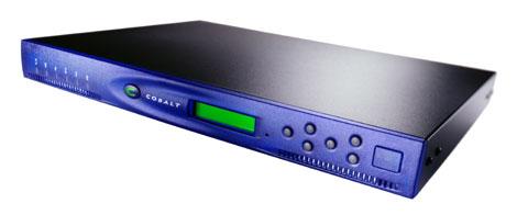
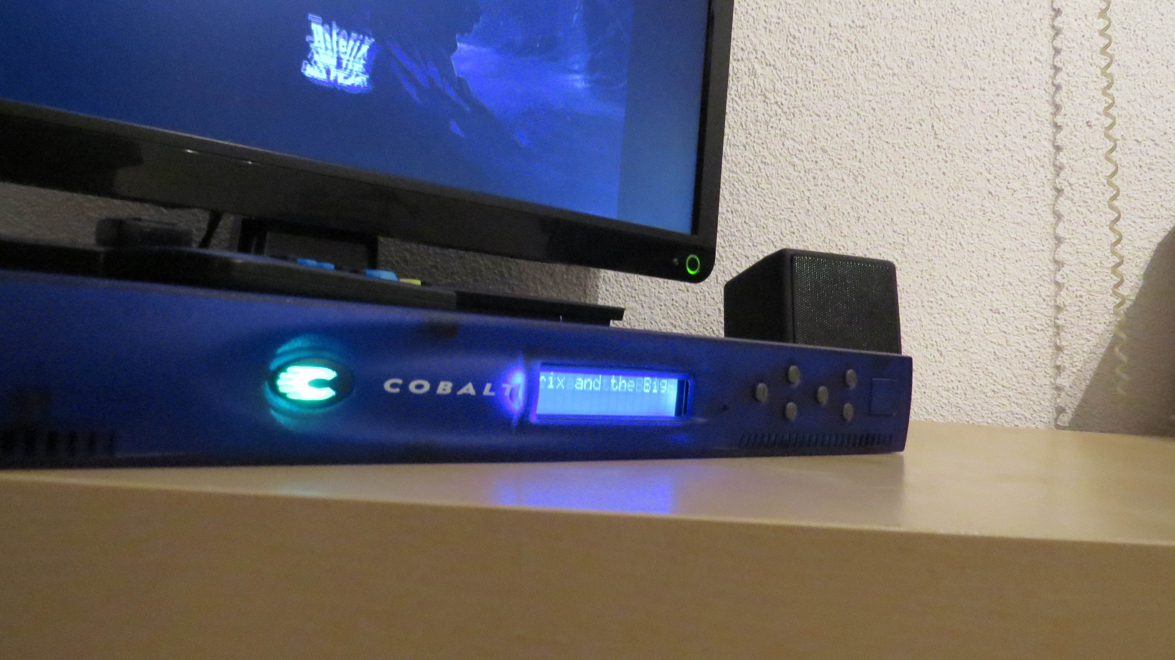
Anyone remember these adorable blueish 1U servers made by Cobalt Networks? While I was never in true love with the Cobalt OS itself, I actually liked the Cobalts Raq enclosure. So much that I salvaged one while cleaning out a data center last summer. I decided to grant it a second live as a media center box running OSMC. And of course it's powered by a Respberry Pi. Nowadays there's simply no way around those nice little boxes ;-) From todays perspective, the specs of the Raq3 are rather low, a 300 MHz AMD K6, barely some 256 megs of RAM and a 20 gig hard drive. Well, back in the days, this was good enough to do simple web hosting. But today, there's not much use to boxes like these. Oh, and if anyone has a Cobalt Cube to donate, let me know. I'll surely put it to good use :-) Anyway, for my current idea to become reality, I first needed some parts. PartsSo here's the things for the shopping list:
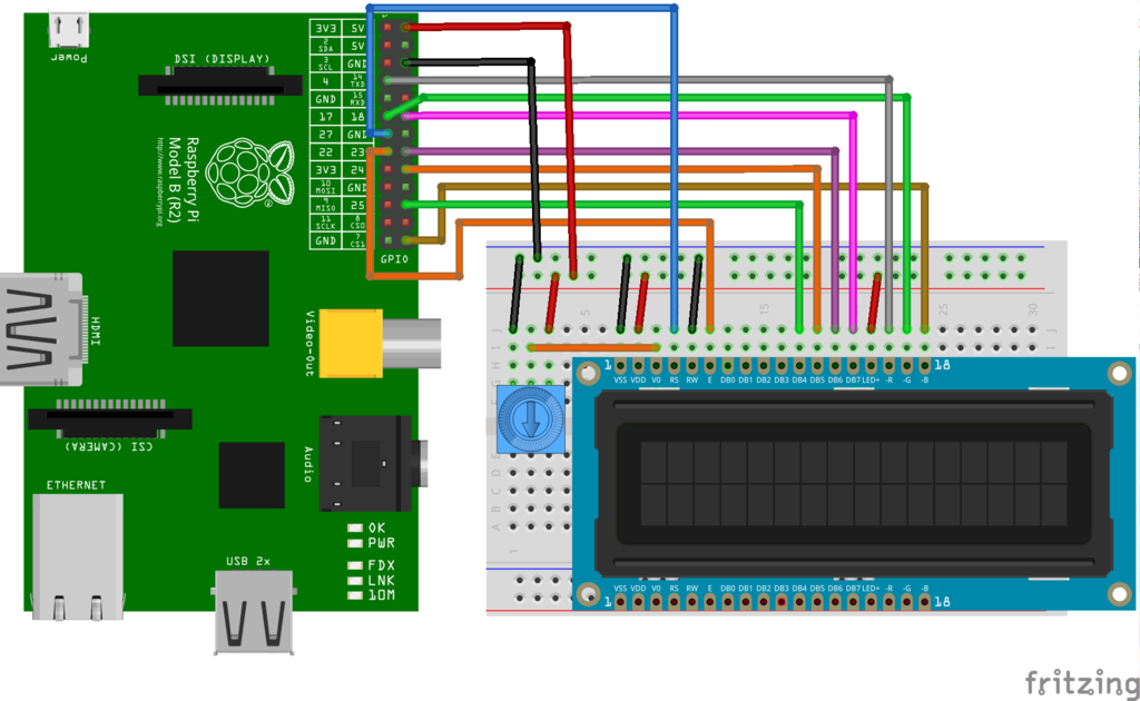
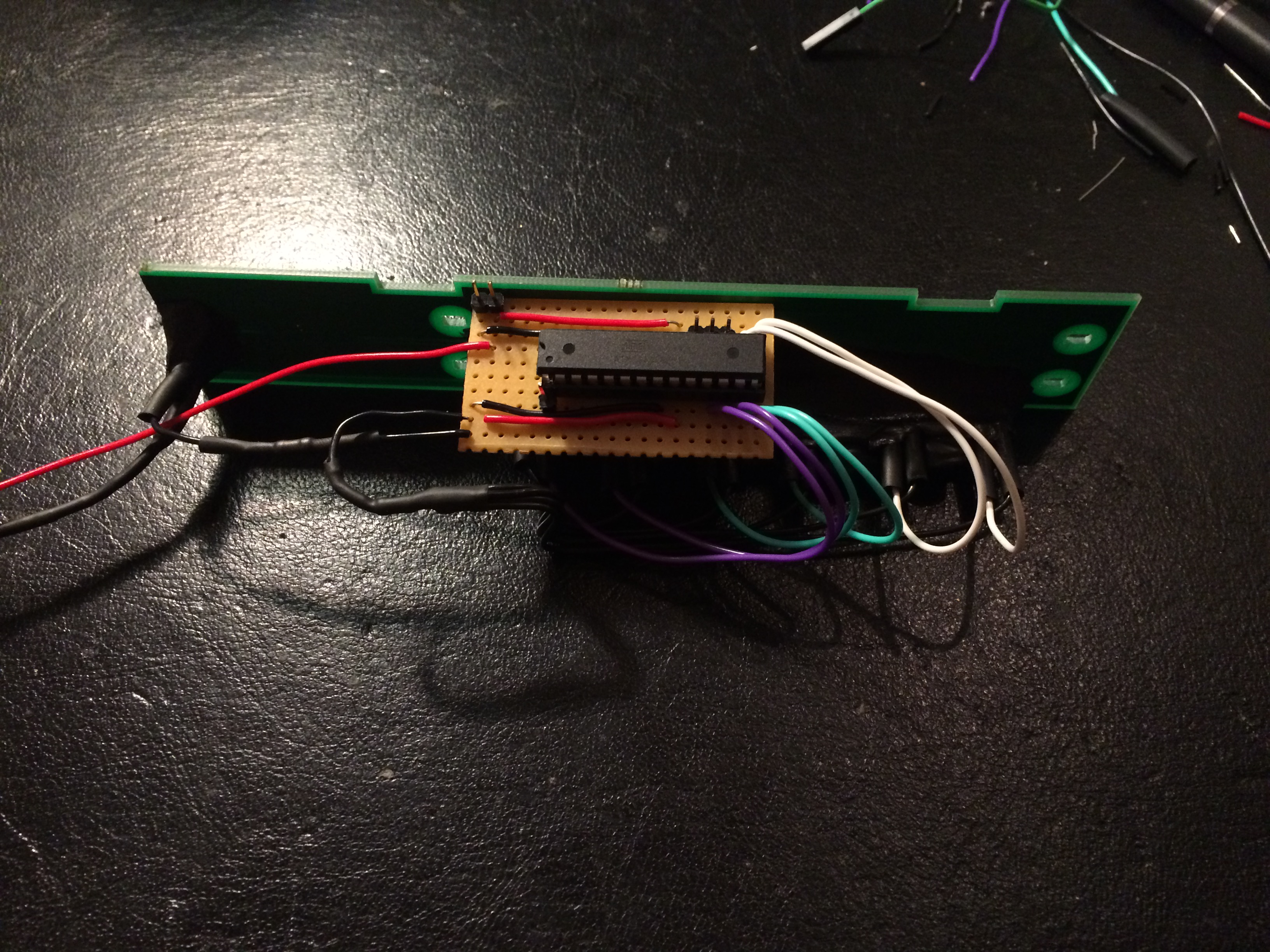
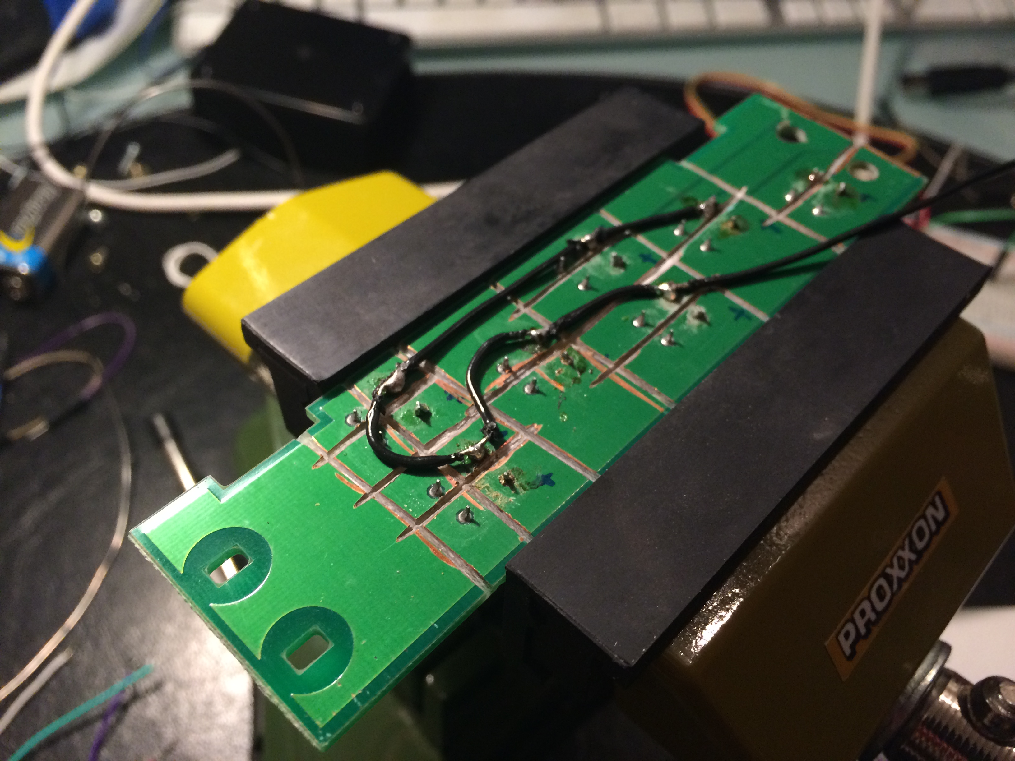
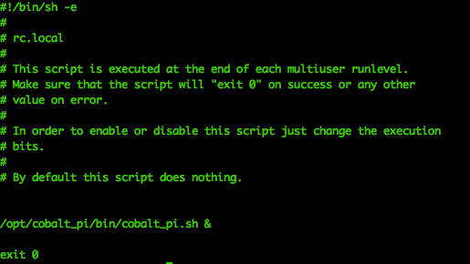
Make new RoomBefore the Cobalt will come to new life, we'll need to yank out the interior. Remove everything except the power supply. The front panel needs to get disassembled as well. I went on and cut them apart using my Dremel. I kept only the right-hand part with the buttons, and the left-hand part with the LEDs. Also keep the mounting bracket which holds the current LCD in place. I scrapped the original LCD panel, as I wanted to replace it with a new one with a blue backlight. If you want to keep the original panel, this is fine as well. Rumour has it, that it has the same pinout than my replacement from Adafruit. Though I did not verify this myself, YMMV. OSMC and Package InstallationSo first I installed OSMC to the Pi. The procedure is straight vorward and documented here. After OSMC is installed, we need some additional packages which are not available by default. Since OSMC builds on Rasbian, it's easy to install additional packages. Connect to your Raspberry Pi through SSH. The default credentials are osmc for both the username and password. Now for the packages: I'm adicted to vim, which is why I installed it. You will need build-essential and python-pip. Also, python2.7-dev is required. Since Python 2.7 is pre-installed on OSMC I stick with it. If you want to go for Python 3, install python3-dev and python3 as well. Also git and python-smbus are required. apt-get update Then let pip build and install the RPi.GPIO library: pip install RPi.GPIO netifaces uptime For the LCD display, an extra library from Adafruit is needed. cd ~ You may want to cleanup this afterwards: rm -rf ~/Adafruit_Python_CharLCD Hooking up the LCDFor the LCD display, there's a great tutorial at Adafruit, which covers the basics on the wiring and more useful instructions. I included the original wiring diagram here as a reference as well. I used this as a starting point to wire up my LCD panel. For the final wiring however, please have a look at the diagram further down below as decided to go a slightly different route. It's especially important to note that I did not connect the backlight controls to the Raspi but rather preferred to hard-wire the backlight to emit blue light constantly. If you went to buy the multicolor LED, you can easily adapt this to use another color or have do the full backlight wiring. Then you will need to stick more closely to Adafruits tutorial. Hooking up the "Glowing LED"The front panel has this nice Cobalt logo sitting right next to the LCD panel. An LED will be hooked up to the Raspberry Pi on GPIO#10. We will be using PWM to get a glowing / pulsating effect on the LED. To achieve this effect, I'll drive the LED at cycle rate between 10 and 100 percent, which means it will actually never be fully turned off. Also I'm using different sleep intervals to reduce the LED brightness more quickly, but give it more time to light up. Here's a code example on how to do it: for dc in range(10, 100, 5): Don't worry, I'll disclose my full code below. This was just to illustrate it. The VU MeterYet more wiring is needed for the VU meter. I decided to build my own VU meter using a ATmega 328 chip, which runs standalone besides the Raspberry Pi. Why is that? Because the Pi doesn't have any analog pins, so I'm unable to perform the analog readout for the VU meter magic. The standalone chip will serve this purpose, so once more I refer to my previous post about incorporating a standalone ATmega. Essentialy it's only about some LEDs hooked up to the IC, then a potentiometer to control sensitiveness of the signal, and the 3.5mm audio jack connected to an analog pin to do the audio detection. Right, we're grabbing audio input off the Pi's 3.5mm audio jack. This also means that you must configure Kodi for dual audio output on HDMI and analog audio. Your audio receiver should therefore be hooked up via HDMI, because there's no analogue audio to re-use, unless you add a twin adapter to the port. Here's the sketch for it. Later on in this article you'll find the complete wiring diagram. Please note that I also added a DIL socket and some headers to the PCB, the former to be able to replace the IC, the latter to hook up an in-system programm (ISP) for to allow for easy software updates without removing the chip. I have included this in my wiring diagram. You'll need extra headers for one pin on +5V, one pin for GND, and the pins 11 (MOSI), 12 (MISO) and 13 (SCK). Have also a look again here. Make Front Panel Keys FunctionalThere's six keys on the front panel (well, actually seven, if you count the reset key as well, I'll spare this one though). This makes it ideal to use them for navigation in OSMC, one key is to serve as ENTER key, one serves as BACKSPACE, the other for will be used as UP, DOWN, LEFT and RIGHT navigation keys. So there's two ways to do it. First I could connect the pins to the Raspi and have it read the key press event, then send a command to Kodi. How to send the command? Either by doing some weird stuff by sending emulated key presses (yeeerks) or by sending the movement commands through the JSON/REST API. But then I found the Adafruit Pro Trinket, which is cheap and still capable enough to emulate a USB keyboard. Yes, that's right, that's exactly what we gonna do. Especially since I've never done it before, this sounded interesting to me. So it's all about connecting the buttons from the front panel to the trinket, check out the wiring diagram further down below for details. One thing is worth noting though: Before you solder some wires to the connector pins on the key panel, make sure that you cut the connectivity of the copper layer of the PCB, so each button has it's own "island". If you don't, the copper layer may cause undesired crosstalk which makes it hard to properly detect the key presses. Software-wise you need only to install the Trinket USB library to your Arduino library folder. Adafruit has a wonderful tutorial about this as well. And be very careful with the Trinket. Do not hit the reset button for too long, or you may erase the boot loader. Also it seems not very fond of sudden disconnects. The only downside I found and yet killed the Trinket three times during my tests so far. To restore the booloader follow the instructions over at Adafruit. Good, but now for the actualy code (download Arduino sketch here), which I hope to be explanatory enough by itself: /* Once you've uploaded the code, each key press should trigger the proper key code being sent to your computer. If you want to be absolutely sure, that all key presses are properly sent, you should use a key code debugger. On OS X, the Key Codes utility can be used. It's free and can be loaded directly from the App Store. It has a simple but yet useful interface which will capture the key press and display some info about. It will help you to see if all works fine. And if you're getting multiple key readings, although you only pressed one key, be sure to cut the PCBs copper layer properly, so the buttons are absolutely 200 % sure not be interconnected to each other in any imaginable way except for the common ground wire. The Wiring DiagramAnd now finally, here's the wiring diagram for everything I talked about so far. cobalt_pi - The heart of it allNow that you've probably wired and soldered everything together, there's still one more thing: *tadadadaaaaa* .... curtain opens .... cobalt_pi[tm] The heart of it all is cobalt_pi, my little python script, which does the magic. But what exactly does it do? Well, first of all, it's a multithreaded script intended to be run at boottime. It will start two threads, one is responsible to drive the PWM for the glowing LED effect, the other is master to the LCD panel. Essentially it's doing a constant poll on Kodi's state, wether there is a player active or not. If the player is inactive, we will display some system information like IP addresses (good to know if Kodi uses DHCP-assigned IP and you need to know it for SSH login), system load, uptime and alike neerdism. On the other hand, if the player is active, the current state is polled via Kodi's JSON/RPC API. This will then be used to show title information and time progress, as seen in many CD/DVD/BD players. Ok, all gadgetery, but still cool. And hey, it's nice to build something like that by yourself :-) Install cobalt_pi like this to /opt directory: This will create a new directory in /opt. The script itself lies beneath /opt/cobalt_pi/sbin/cobalt_pi.py. It's intended to be run via a shell script, which you should add to your /etc/rc.local file. Add a line like this before the exit 0 line ... ... so it will look similar to this: Before you start it, be sure to edit the /opt/cobalt_pi/etc/cobalt_pi.ini config file. All relevant settings are configurable via the ini file, so you won't really need to touch the code if you need to change the pins or Kodi's JSON/RPC url: [gpio] GPIO_PL1=10 GPIO_RS=25 GPIO_EN=24 GPIO_D4=23 GPIO_D5=17 GPIO_D6=27 GPIO_D7=22 GPIO_BACKLIGHT=0 [lcd] LCD_COLUMNS=16 LCD_ROWS=2 Bringing It All TogetherRight, so once you've got everything in place, this is what you get: Mission: Accomplished! |
| Powered by [ Universal Post Manager ] plugin. HTML saving format developed by gVectors Team www.gVectors.com |