|
This page was exported from phaq
[ http://phaq.phunsites.net ] Export date: Wed Apr 24 22:49:15 2024 / +0000 GMT |
|
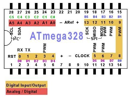
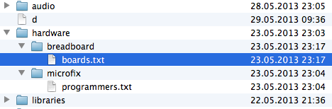
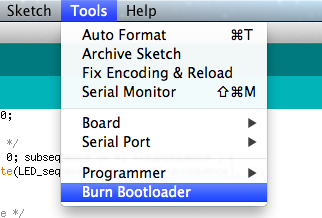
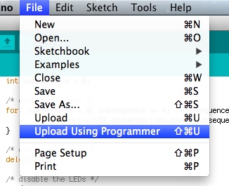
**** UPDATED 2018/04/27 *** Arduino is super cool, I really love that thing, but ... Who would really want to put a fully-featured Arduino board into each and every project, at least when they're built to more like a permanent setting? I guess nobody. Honestly, an Arduino is not expensive to buy, but to expensive, if you want to put dozens of them in place. So, why not put just the ATmega chip, which drives every Arduino at its heart, inside and leave all the rest away? This is what this post The RRRRRRRRRRBBA, a $3 Arduino talks about: Just provide power to the ATmega and get rid of all the bells and whistles. You can even spare the oscillator and the resistors. Well, this is exactly what I wanted. But since I didn't have the proper gear at hands to flash the ATmega chip, I first had to look into another topic, namely how to turn your existing Arduino into an ASP (in-system programmer). Here's some of the pages I came along: Arduino ISP Arduino to Breadboard The Arduino Micro schematic Arduino Leonardo as ISP Arduino Micro as ISP and atTiny84A But I soon found that doing so with an Arduino Micro, the only one I had available at that time, is not as straight forward as with other Arduino boards. So I did this writeup to cover my findings on this. My reading covered at least a dozen of other sites as well, and I must admit, that I didn't take note about each and every of thee. If you find that I'm missing some credit to your site, drop me a note so I can add it here. Step #1 - Prepare Arduino Micro as ISPFirst you must install the ISP sketch to your Arduino Micro. You should find this at File - Exmaples menu as ArduinoISP. This should bring up the sketch in the editor. Please check that the first line says "ArduinoISP version 04m3",otherwise you may want to fetch the current version GitHub. Now scroll down the file a bit to find this line:#define RESET SS Replace it to this: UPDATE 2018-04-27: I recommend using the version of ArduinoISP that comes with current version (1.8+) of Arduino IDE. This one is also set to "RESET 10" by default. Nevertheless, a quick inspection of the ArduinoISP source is still required. My tutorial refers to the "new-style wiring". However, I have now also tried it using an Arduino Duemilanove, where I hooked up the MOSI, MISO and SCK pins to pins 11, 12 and 13 respetively. So if you happen to use that setup, checkout this section of the source code: // Uncomment following line to use the old Uno style wiring Remove the commented out line "#define USE_OLD_STYLE_WIRING" to make it work with old style wiring. Step #2 - Upload the SketchRight, now you need to change the IDE settings to support your Arduino Micro. If not yet done so, check your Tools - Board menu and make sure that Arduino Micro is selected. Then upload the ArduinoISP sketch to your Arduino Micro. If all goes smooth you should end up with your Arduino being an ISP (in-system programmer). Now, please disconnect your Arduino from USB and close the IDE. Step #3 - Hookup Arduino Micro and ATmega 328Now wireup your Arduino Micro and the ATmega 328 on the breadboard as in the following diagram. Note that you MUST connect the MOSI, MISO and SCK connectors to the ICSP header. The drawing from Fritzing is a bit off to the left, so it's the lower left (white wire), lower center (orange wire) and upper center (green wire) connectors. Please DO connect RESET to PIN 10 of the Arduino Micro as shown. Step #4 - Configure IDE to support Arduino on BroadboardFor your IDE to support the Arduino Micro, you must some new config files in your Arduino folder. Beneath your hardware/broardboard directory (create it if it should be missing), create a new file boards.txt (or append to an existing one, of course) with the following content: atmega328bb.name=ATmega328 on a breadboard (8 MHz internal clock) The above is really needed. Since our goal is not to use resistors and oscillators, the ATmega will only run at 8 MHz, which is why we need to enable this specific configuration. Then go to the hardware directory and create a new directory called microfix and save these lines a file called programmers.txt therein: arduinoispmicro.name=Arduino as ISP on Micro arduinoispmicro.communication=serial arduinoispmicro.protocol=arduino arduinoispmicro.speed=19200 Now start the IDE, then go to Tools - Programmers menu. You should find a new entry called Arduino as ISP on Micro. Select this as your default programmer. In Tools - Board menu select ATmega328 on a breadboard (8 MHz internal clock). Step #5 - Installer Boot LoaderNow connect your Arduino Micro to the USB port, and in the IDE go to Tools - Burn Bootloader. This should actually burn the special boot loader to the standalone ATmega 328 controller. Step #6 - Upload SketchFinally open your favorit sketch and go to File - Upload using Programmer. This Will install your sketch directly to the ATmega 328 controller. Step #n - DoneYou're all done. Unplug the Arduino Micro and remove the ATmega 328 from the breadboard. You can now hook it up to your own project without the need to rely on the full-blown Arduino board. To ease maintenance, I recommend using a 28-pin DIL socket or even a ZIF socket to easily remove and/or the controller. You could even add some connections to the MOSI, MISO, SCK and RESET connectors, so you could just hook up your Arduino for easy reprogramming without removing it from your project. In fact, it used this for another project of mine A CPU for K.I.T.T. (german language only), where the ATmega standalone chip complements a Raspberry Pi. |
| Powered by [ Universal Post Manager ] plugin. HTML saving format developed by gVectors Team www.gVectors.com |